Hardware-in-the-Loop (HIL) and Real-Time Simulation Help Honda Accelerate the Commercialization of its HondaJet Echelon

“The flexibility and power of the Pickering systems has proven itself in our sustaining and development environments… also, the team at Pickering went above and beyond what we were expecting and helped us develop a robust hardware and software package that will expand the capabilities of our aircraft development labs.” - Michael Hodgson, Senior Engineer, Integration Test Facility

Hardware-in-the-Loop (HIL) and Real-Time Simulation Help Honda Accelerate the Commercialization of its HondaJet Echelon

With an intended range of 2,625 nautical miles (nm), a maximum cruise speed of 450 knots true airspeed (KTAS) and a maximum cruise speed of flight level (FL) 470, Honda Aircraft Company’s HondaJet Echelon is aiming to set new standards in performance and comfort. It is also extremely fuel efficient and is set to be the world’s first light jet capable of nonstop transcontinental flight across the United States. 

The concept for the aircraft was unveiled in 2021 at the NBAA Business Aviation Convention & Exhibition (NBAA-BACE) in Las Vegas, and Honda’s plans to commercialize the concept were formally announced in June 2023. Honda is aiming for type certification in 2028. 

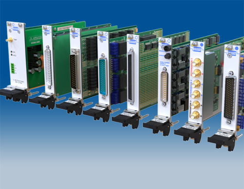
The aircraft features many advanced electronic systems including cockpit avionics, mechanical systems controllers, advanced flight controls, and safety systems. All comprise multiple line replaceable units (LRUs), with upwards of 50 in total on the aircraft. 

Many LRUs interface with one or more sensors, including linear and rotary variable differential transformers (LVDTs and RVDTs, respectively), thermocouples, and other transducers. Communication between the LRUs is via industry-standard buses, including Ethernet, ARINC-429, and RS-232, -422, and -485. 

The HondaJet Echelon has about 3,000 signals, many of which must be processed in real-time - i.e., within milliseconds and in a completely deterministic way—as they are required by systems providing safety-critical functionality.

Application Driven Development 

Understandably, developing an avionics suite for a new aircraft is no easy feat, even if LRUs from other aircraft in Honda’s range can be re-used, either as they are or with some modifications. The reason for this is that every time an LRU receives a hardware revision and/or software update, its functionality and interoperability with other units must be verified. Individual LRU and full system verification is therefore a complex and rigorous process. 

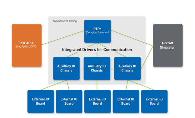
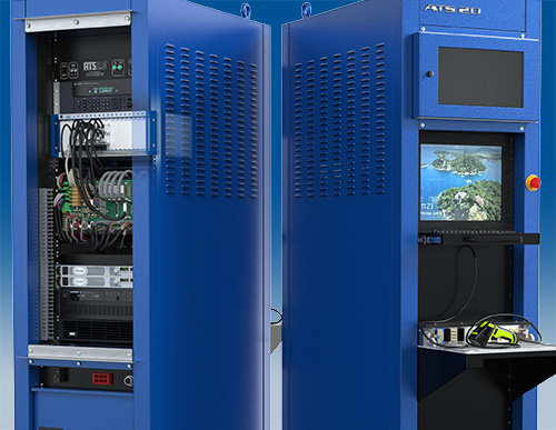
System integration is performed with both hardware and software-in-the-loop (HIL and SIL, respectively) using a dedicated platform (see Figure 1). It is effectively most of the HondaJet Echelon’s fuselage and cockpit, fitted with the avionics suite’s wiring looms and slots for the LRUs under development. However, the platform does not include real LVDTs, RVDTs and other sensors. Instead, these are simulated. All system development work is being carried out at Honda’s dedicated Advanced System Integration Test Facilities (ASITFs) in Greensboro, North Carolina facility.

Honda's platform for HondaJet Echelon HIL/SIL system integration

Figure 1 – Honda’s platform for HondaJet Echelon HIL/SIL system integration

“With simulation, we can achieve everything that we can with real transducers, but with the added bonus that we can more easily perform fault injection and monitor signals. This is effectively a test-driven development strategy as we can iterate on design, and it’s allowing us to accelerate the pace of aircraft development, reduce costs, and give us more confidence when we go into certification.”
- Michael Hodgson, Senior Engineer, Integration Test Facility

The platform for the development of the HondaJet Echelon’s avionics was built by a third party, a HIL systems integrator. Initially though—while the system could do much of the real-time testing required for system integration and verification—LVDT, RVDT and certain switching components could not be accommodated within the system and were simulated on boards made by the third party. Residing outside of the synchronized timing zone (see Figure 2), they were not real-time.

Architecture of the original system integration platform
Figure 2 – The architecture of the original system integration platform.

Honda turned to Pickering Interfaces for help in creating a more integrated solution, one that could cope with a higher density of signals in real time. Pickering’s solution took the form of its 18-slot LXI/USB modular chassis and a variety of simulator modules. The chassis is fully compliant with the LXI Standard 1.4 and allows 3U PXI modules to be installed and controlled through a standardized Gigabit Ethernet interface or via a USB interface.

As for the modules, they are: 

  • One PXI Millivolt Thermocouple Simulator (41-760-001). This is a multichannel simulator, where each channel provides a low-voltage output across two connector pins capable of providing ±20mV with 0.7µV resolution, ±50mV with 1.7µV resolution and ±100mV with 3.3µV resolution, covering most thermocouple types. 
  • Four PXI/PXIe LVDT/RVDT/Resolvers (41/43-670-001-ABBC). It has four banks, each capable of simulating the output of a single 5- or 6-wire LVDT/RVDT or resolver, or dual 4-wire utilizing a shared excitation signal. This allows the module to simulate up to four channels of 5- or 6-wire or eight channels of 4-wire. 
  • Six 83x SPDT High-Density 2A PXI Relay Modules (40-100-001). This module was designed for use in the aerospace and defense sectors and is suitable for applications requiring switching up to 2A at voltages of up to 200VDC or 140VAC. 
  • One PXI 20x SPST 10A Power Relay Module (40-160-003). This module is suitable for switching inductive/capacitive loads up to 10A at 250VAC. 
  • Three PXI 48-channel Resistor Modules (40-280-121). Each channel can be programmed as a short circuit, an open circuit, or a fixed resistor value. 
  • Two PXI 128x2 Matrix Modules, 1-Pole (40-584-001). Each switch can handle up to 2A (hot or cold switching) and 60W. 
  • One PXI/PXIe 16-Channel Analog Output / Current Loop Simulator (41/43-765-001). It consists of up to four 16-bit, digital-to-analog converters (DAC), capable of creating four current outputs each. A ±24mA mode gives the module the ability to simulate sensors that provide or sink current.

Though the above are all PXI or PXIe modules, by using the LXI chassis, they are treated as LXI-compliant devices controlled by a driverless soft front panel. 

Integration of the LXI unit into the third-party framework was a challenge, though. Hodgson recalls: “We determined that the LXI needed to communicate with the real-time simulator via Ethernet. However, the drivers supporting this functionality were not compatible with the third-party framework.”

In a collaborative effort with the software team at Pickering Interfaces, Honda’s engineering team was able to develop a special communications package that allowed the LXI system to drive the PXI modules from the third-party real-time framework. Hodgson: “So now our test routines tell the real-time software to communicate with the LXI chassis to move a virtual LVDT to a certain position, for example.”

Cabling designed by HondaJet and integrated by Pickering is used to interconnect the Switching asset I/O from an interconnect panel to the simulation test rig. Figure 3 shows the architecture of the now fully integrated real-time system.

HondaJe architecture of the enhanced system integration platform
Figure 3 – The architecture of the enhanced system integration platform.

The Results 

The HIL integration system became fully operational (i.e., fully controllable in real-time) in mid-2023 and has enabled Honda to shorten the time to test, in turn enabling the company to accelerate its HondaJet Echelon development program.

Honda has more than 1,900 automated test cases for the HondaJet Echelon, where these tests are written in a combination of C# and Python: C# to provide an interface and Python to provide the functionality connecting to the APIs. “For example, we automate crew alerting system (CAS) CAS testing,” explains Hodgson. “We automate that for FAA accreditation. We have test management software that then operates on the API against the real-time software.”

Impressed by the results, Honda has not only subsequently retro-fitted the ASITF lab originally built to develop the HondaJet HA-420 aircraft with multiple Pickering LXI systems but also plans to include the use of Pickering’s simulators elsewhere within its ASITF facilities.

“The flexibility and power of the Pickering systems has proven itself in our sustaining and development environments,” concludes Hodgson. “Also, the team at Pickering went above and beyond what we were expecting and helped us develop a robust hardware and software package that will expand the capabilities of our aircraft development labs.”

HondaJet Chassis For Pickering Interfaces
Above, Pickering’s LXI chassis contains several simulator modules that can be controlled and react in real time. 
As an integrated solution, it is saving Honda (test) time and money.


Want to learn more about Sensor Simulation? Check it out here.