Automating Fault Insertion Tests to Improve Software Quality
Pickering Interfaces supports ECU Testing in automating the fault insertion process, helping Automotive Manufacturers run more test cases in a shorter period of time.
 Testing Engine Control Units (ECUs), especially safety related models, is as much about software testing as well as hardware
these days—this is due to the increased intelligence required within ECUs to control braking, prevent rollovers, and
ensure that power is applied to the correct wheels in a compromised driving mode. Automotive manufacturers such as Magna
Powertrain, Delphi, and Continental have the same concerns for testing the safe operation of their products.
Testing Engine Control Units (ECUs), especially safety related models, is as much about software testing as well as hardware
these days—this is due to the increased intelligence required within ECUs to control braking, prevent rollovers, and
ensure that power is applied to the correct wheels in a compromised driving mode. Automotive manufacturers such as Magna
Powertrain, Delphi, and Continental have the same concerns for testing the safe operation of their products.
For this article, we will focus on automotive transfer cases. A transfer case is a mechanical/electronic device that monitors wheel slippage and ensures that power is applied to wheels that are not slipping.
As part of the design process, manufacturers run a series of tests to ensure that the software that controls their transfer cases reacts to system failures, such as open, shorted, and cross/inline resistance connections, in a predictable and safe manner. Ultimately, this improves customer satisfaction and reduces warranty costs.
In one instance, a manufacturer developed a test fixture that allowed them to manually inject faults. While this fixture was effective, having to manually switch in faults was quite time-consuming—this limited the number of tests cases that they could run on a particular unit. Also, a manual fixture often requires more frequent maintenance, further slowing test times. Finally, it was also prone to operator error, which can compromise test results.
That's what lead them to call on Pickering. These products include Fault Insertion Unit (FIU) switching solutions for Hardware-in-the-Loop (HIL) simulation applications and Programmable Resistors. The FIU switching modules can be used to introduce electrical faults into a system, which typically duplicates various conditions that can occur because of corrosion, short/open circuits, and other electrical failures, inherited through age, damage or even faulty installation.
Using Pickering fault insertion modules to automate the fault injection process, they can run more test cases in a shorter period of time, with the result being that their testing is more repeatable, comprehensive and they can find and fix problems earlier in the development cycle.
Finding faults
A transfer case is used to distribute power from a vehicle's transmission to the front and rear axles. One example is the Double Speed Active Transfer Case or ATC. The ATC features include a multi-plate wet clutch, electromechanical shift actuation, and chain driven front output. The system guarantees dynamic torque distribution between the front and rear wheels and can be tuned to provide desired vehicle performance characteristics in varied terrain and inclement weather.
As part of the TCCM (Transfer Case Control Mechanism), a transfer case Electronics Control Unit (ECU) controls the operation of the transfer case. It connects to sensors and actuators in the transfer case, as well as interfaces with the vehicle's Controller Area Network (CAN). When a driver shifts into gear, the transfer case ECU receives the command and then determines if it can perform this shift or not. After it has successfully performed a shift, the transfer case ECU reports this to the network.
In operation, many different faults can occur. For example, consider an eight-conductor cable that connects actuators and sensors in the transfer case to the control module. These connections can fail open or short to adjacent conductors, in addition, high-resistance connections and high-resistance shorts can develop as automobiles age, and these can cause a transfer case to fail in the field.
To ensure that the transfer case will operate safely under fault conditions, transfer case manufacturers simulate these faults in their Controls lab.
Hardware-in-the-loop testing has become a very popular way to test the electronic control units, such as the transfer case ECU, used in today's automobiles. An HIL simulator can provide all of the inputs and outputs of a vehicle without the need for actually building prototype vehicles. It saves ECU manufacturers a lot of money, not only because they don't have to build prototype vehicles, but also because they can perform exhaustive testing in a laboratory instead of on a test track or dynamometer.
They can even test a transfer case ECU without actually having the mechanics of a transfer case. In this mode, the HIL test system simulates the transfer case in addition to the rest of the vehicle.
To test the transfer case ECU software, designers developed a number of different operating scenarios. These include vehicle startup, shutdown, and driving scenarios designed to put a transfer case control module through its paces. For example, in one scenario, a transfer case is commanded to go to its desired position. Other scenarios exercise various other product features (various shift scenarios, cold crank profile, voltage profiles, etc.).
When the manufacturer in question first started doing this type of testing, they built a test fixture, shown in Figure 1, called a breakout box, to manually insert faults. The breakout box was inserted between a transfer case and its control module, and a technician would manually switch faults in and out. As mentioned earlier, this limited the number of tests cases that they could run in any given time frame, required more frequent maintenance, slower test times, and are also prone to operator error, which can compromise test results. While this method was an effective way to get started, it was clear that there was much room for improvement.

Figure 1: Generic breakout box design used for bench testing
Arguably, the most problematic thing about manually inserting faults is that running a series of tests takes a long time. Using the breakout box, it took up to eight minutes to run a single test case. Since they run thousands of test cases, it was evident from the start that they would have to find a way to reduce the test time.
Another disadvantage of manually inserting faults in this way is that they could only insert shorts and opens. To more thoroughly test the transfer case ECU, they also needed to be able to insert resistive faults as well as hard opens and shorts.
A third issue with manually inserting faults this way is that the breakout boxes are hard-wired, and are, therefore, not very flexible. To test different transfer case ECUs or different product configurations, the Test Engineering department would have to build a new breakout box or re-wire an existing one. Doing this is costly and time-consuming.
Automating fault insertion
Clearly, manufacturers have been thinking about how to automate fault insertion. This particular transfer case manufacturer’s goals were not only to speed up test execution but also add the capability to insert resistance faults and to make the test equipment a little more universal. Achieving these goals, they reasoned would allow them to simulate more real-world faults, with the result being a more solid product.
After evaluating switching systems from several vendors, this customer identified Pickering Interfaces products as a promising solution. They purchased a 19-slot PXI chassis populated with several PXI bus modules ( our PXI 30A Fault Insertion Switch Module, (model 40-191) shown in figure 2) to simulate shorts and opens. This module provides a robust solution to high current fault insertion. It uses solid state switching elements and is capable of carrying 40A on single channel or 30A on all channels at the same time. It is designed to insert three different fault conditions between the test fixture and the equipment under test, including open circuits, short circuits between UUT connections, and short circuits to external signals.
Solid State Relays on each channel enable the test system to set signals to the UUT to open-circuit. Fault-insertion buses allow any channel to be shorted to any other channel and also enable any channel to be connected to an external signal such as Power, Ignition or Ground to simulate fault conditions. The module is supplied with two fault buses.
Because faults aren't always completely open or hard shorts, our Programmable Resistor Modules (model 40-295), shown in figure 2, are used to simulate high-resistance faults. This module provides up to 18 fully isolated variable resistors at eight-bit resolution or ten fully isolated variable resistors at 16-bit resolution. The resistance of each of the channels can be set between 0 ohms and 16 MΩ.

Figure 2: PXI 30A Fault Insertion Switch Module, model 40-191 |

Figure 3: PXI Programmable Resistor Module, model 40-295 |
Figure 3 shows how the switching system connects the HIL simulator, the transfer case ECU being tested, and the transfer
case, if an actual transfer case needs to be part of the test.
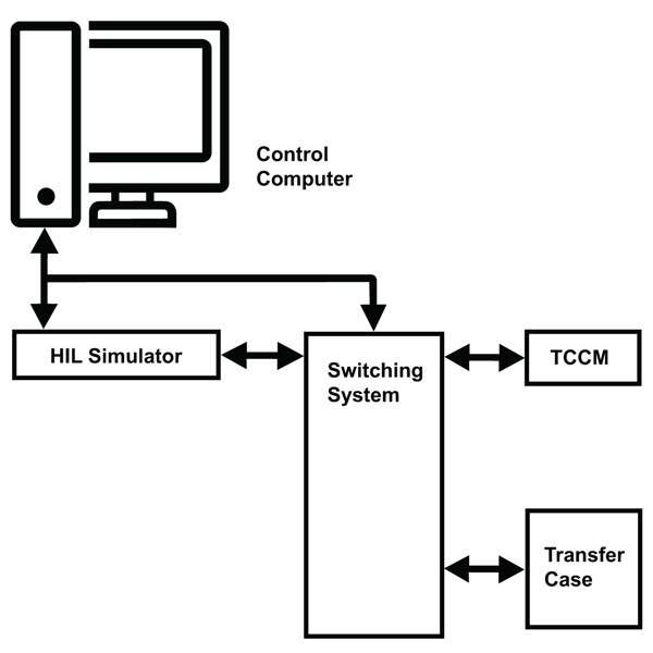
Figure 3
The switching system is used to inject all of the potential faults. For example, to inject open faults, they simply have to open the line. To short two lines, they connect each of the two lines to a Fault Insertion module and connect the two signals to one of the module's fault busses. To simulate a short to power or ground, they connect the signal line to one of the fault busses and then connect that bus to ground or to an external voltage.
To inject a resistance fault into one of the signal lines running between the transfer case and the transfer case ECU, the control computer would command the switching system to switch in one of the variable resistors on the 40-295 Programmable Resistor Module. Next, they vary the resistance in discreet steps: 0Ω, 5Ω, 10Ω, 20Ω, 50Ω, 100Ω, 200Ω, 500Ω, 1,000Ω, and so on until they reach 1 MΩ, or until the line reacts like it is an open circuit.
Once a fault has been inserted, they run one or more driving scenarios and gather test data. One of the most significant bits of data they gather is the current that the system is drawing. An unusually high current is a sure sign of problems. They look at a number of other parameters, too, though. These include CAN signals and Electrical signals being generated by the transfer case ECU and overall system behavior.
By automating the fault insertion, the time it takes to run a single test case has been cut from eight minutes on average to around four minutes—this is a huge savings when you consider that a typical test run might include 20,000 test cases and take more than a month to run completely. It has also allowed the manufacturer to reduce the elapsed time it takes to run a complete test. With manual insertion, a technician or test engineer had to be present to switch faults in and out. Now, however, personnel only need to be present when risky tests are being performed, as most tests are run overnight with no supervision needed.
Interestingly, the time-savings are not necessarily used to make the test runs shorter, but to run more test cases, such as those that include resistance faults, in the same amount of time. Using the test time to improve test effectiveness is an indication of the emphasis that companies puts on software quality and reliability.
Analyzing the test results
As you can imagine, these tests generate a very high volume of test data, and analyzing this data is a big task. The first thing they look for is whether the test has caused any damage to the UUT. No faults should damage the transfer case of the transfer case ECU, so any indication that the unit has been damaged throws up a red flag.
If none of the test cases have caused any damage, they start analyzing the rest of the test data. Of particular interest at this point are the CAN signals and overall system behavior. What they are looking for is data that would indicate unintentional motor movement in a transfer case. They might also check to see that the transfer case ECU generated the appropriate diagnostic codes.
Analyzing the test data is a team effort—the team not only includes the test engineers, but also the mechanical engineers, electronics engineers, and software developers that designed the transfer case. By working as a team, they are not only able quickly find areas of concern but are also able to complete the fixes faster.
The future is automated
While the customer’s Engineering team is very pleased with the way that the Pickering switching system has allowed them to automate their test, they realize that this is only the beginning. For example, instead of building separate test fixtures for each transfer case, they are working on a “universal” test system for their transfer cases. Using a computer-controlled switching system, they feel that they can accomplish this.
Another hurdle that manufacturers will have to jump is figuring out how to reduce the time it takes to analyze the test data. Automating fault insertion has allowed them to run many more tests, but it has also increased the amount of time they must spend analyzing the test data. That being the case, there's an effort underway to automatically analyze the test data. Developing a tool that would automatically flag test data that might indicate a problem would save them a lot of time.
An effort is also underway to reduce the number of test cases. In our customer’s case, their Engineering thinks that they can do this by identifying test cases that are really testing the same thing and eliminating them from the test program. It should also be noted that often a subset of the test cases developed in NPI are used in the product test strategy. This tactic provides for consistent test results compared to NPI measurements and speeds the production test development.
Pickering products helped Engineering introduce “SMART Automation” in testing additional failure modes (inline resistive faults, cross shorts, and cross resistive shorts) under dynamic vehicle conditions that lead to better product quality.
The bottom line for this phase of testing, Pickering Interfaces supports ECU manufacturers in automating the fault injection process, helping them run more test cases in a shorter period of time.